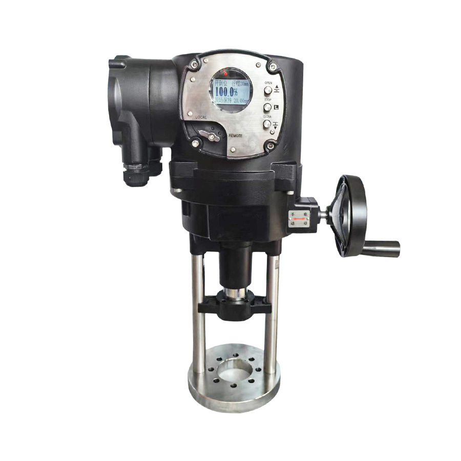
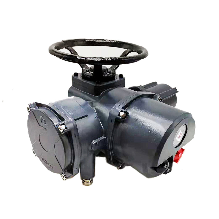
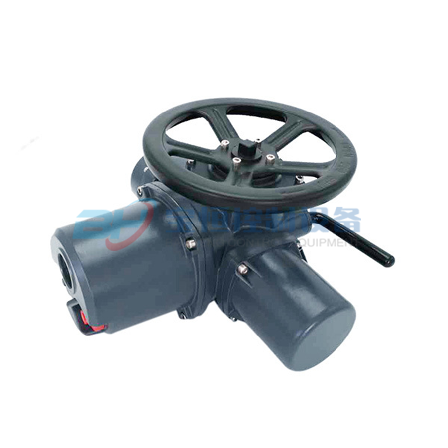
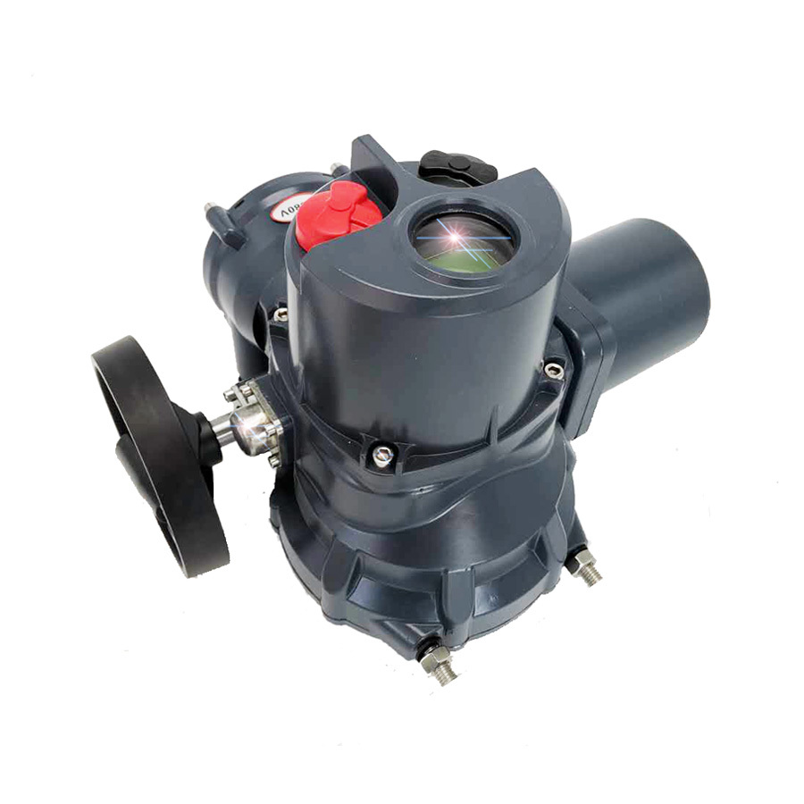
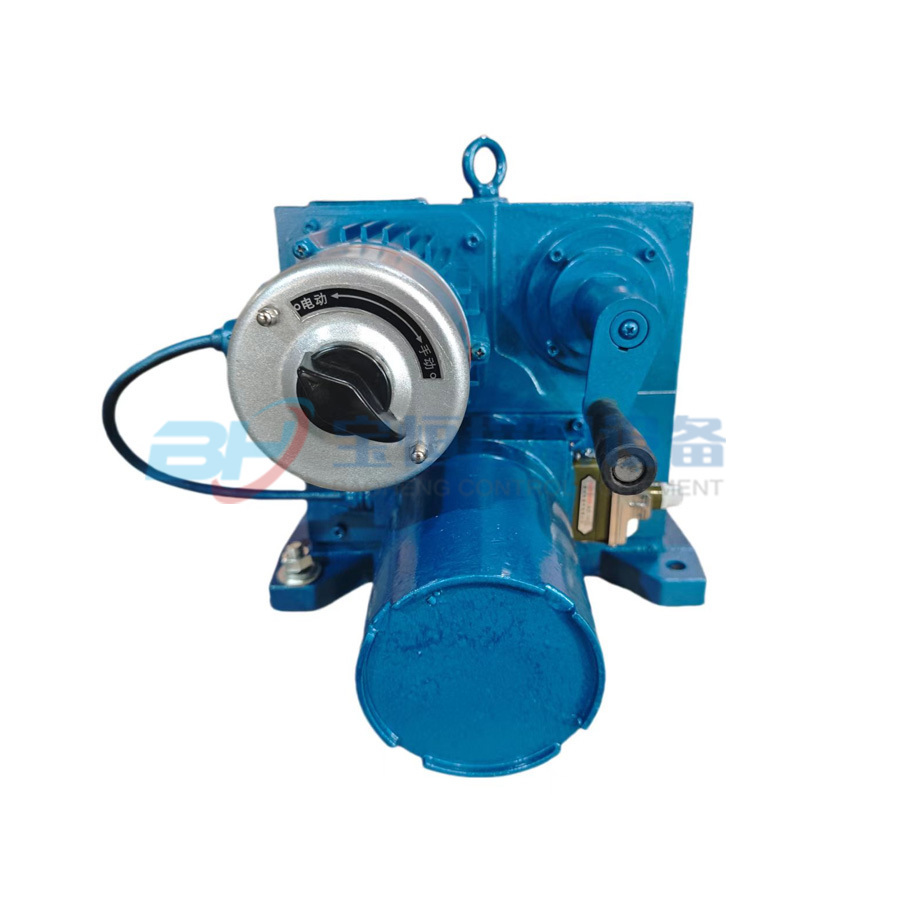
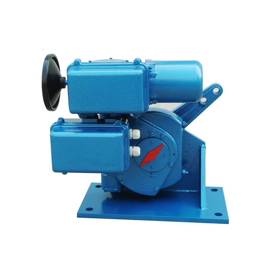
ZSLD Pneumatic Long Stroke
The pneumatic long-stroke actuator (referred to as long-stroke) uses compressed air as the power source, receives pneumatic and electrical analog signals or intelligent signals, outputs angular displacement, and drives the regulated mechanism with a certain torque—this is a type of angular stroke actuator.
Keyword:
- Commodity name: ZSLD Pneumatic Long Stroke
1. Overview
The pneumatic long-stroke actuator (referred to as long-stroke) uses compressed air as the power source, receives gas and electric analog signals or intelligent signals, outputs angular displacement, and drives the regulated mechanism with a certain torque—this is a type of angular stroke actuator.
For different users, our company has developed three series: A, I, and II, among which the A type has the most complete functions, differing structurally from types I and II. The long-stroke of types I and II comes with separate instructions.
This series of actuators can carry multiple functions, and the products come with protective casings, allowing them to be used in relatively harsh conditions. They can be widely used in sectors such as electric power, chemical engineering, and petroleum.
2. Classification
1. Classified by the type of manual operation mechanism
Type A: with a cover, manual operation is wheel-type, with the most complete functions.
Type I: manual operation is wheel-type;
Type II: manual operation is lever-type, the mechanism is the lightest.
2. Classified by the type of control signal received
ZSL type: receives gas signals of 0.02 to 0.1 MPa;
ZSLD type: receives 4 to 20 mA analog or intelligent electrical signals;
3. Classified by output torque into types of 250Nm, 400Nm, 600Nm, 1000Nm, 1600Nm, 2500Nm, 4000Nm, 6000Nm, 60000Nm, etc.
3. Main Technical Parameters
Main technical parameters are shown in Table 1
Basic technical parameters | |||||
Input signal | 0.02-0.1 MPa gas signal; 4-20 mA analog or intelligent signal | ||||
Output angle | 0-90° | Operating pressure | 0.5MPa | Basic error | ≤±1.5% |
Hysteresis | ≤1% | Dead zone | <0.6% | Static gas consumption | <1500L/h |
Operating environment temperature | -25 to 55 degrees Celsius | Specification and torque | See Table 2 | Cylinder parameters | See Table 2 |
Optional function configuration parameters - signal feedback | |||||
Feedback signal | 4-20 mADC | Feedback working power supply | DC24V | Basic error | ≤±1.5% |
Optional function configuration parameters - three-break protection | |||||
Working power supply | AC220V | Signal closing threshold | <1.8mA | Signal opening threshold | >3.4mA |
Gas source closing threshold | <0.35MPa | Gas source opening threshold | >0.45MPa | Response time | <0.4S |
Optional function configuration parameters - start and end stroke switches | |||||
Adjustable range | 0-20°; 70-90° | Contact capacity | AC220V 1A or DC24V 3A | ||
Table 2
Nominal torque | Cylinder inner diameter | Piston stroke | Calculated torque | No-load full stroke time | Full load full stroke time | |
Maximum | Minimum | |||||
N.M | mm | mm | N.M | < seconds | < seconds | |
250 | 100 | 160 | 440 | 310 | 5 | 10 |
400 | 130 | 160 | 750 | 530 | 5 | 10 |
600 | 130 | 250 | 1160 | 820 | 5 | 15 |
1000 | 160 | 250 | 1760 | 1250 | 10 | 15 |
1600 | 200 | 250 | 2770 | 1960 | 10 | 25 |
2500 | 200 | 400 | 4000 | 3140 | 20 | 25 |
4000 | 250 | 400 | 6900 | 4900 | 20 | 30 |
6000 | 300 | 400 | 10700 | 7060 | 20 | 30 |
8000 | 2×250 | 400 | 13800 | 9800 | 25 | 35 |
Note: The calculated torque in Table 2 is the calculated value when the angle range is 0-90, operating pressure is 0.5 MPa, and efficiency is 100%. The output torque is minimum at 0° or 90°, and maximum near 45°.
Message


