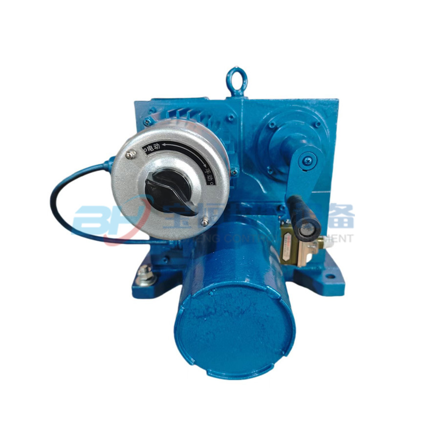
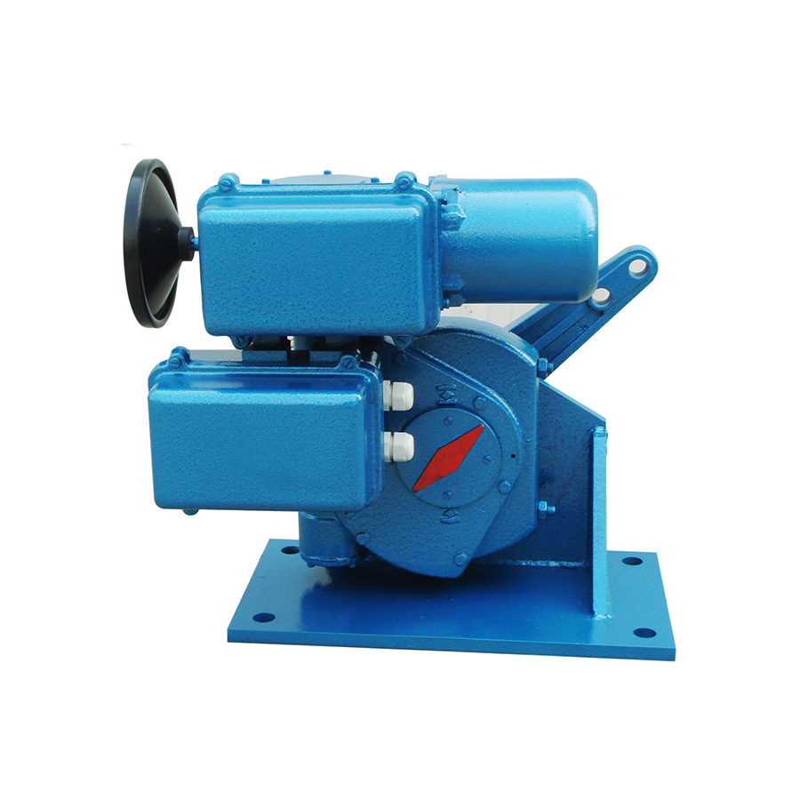
YMD Series
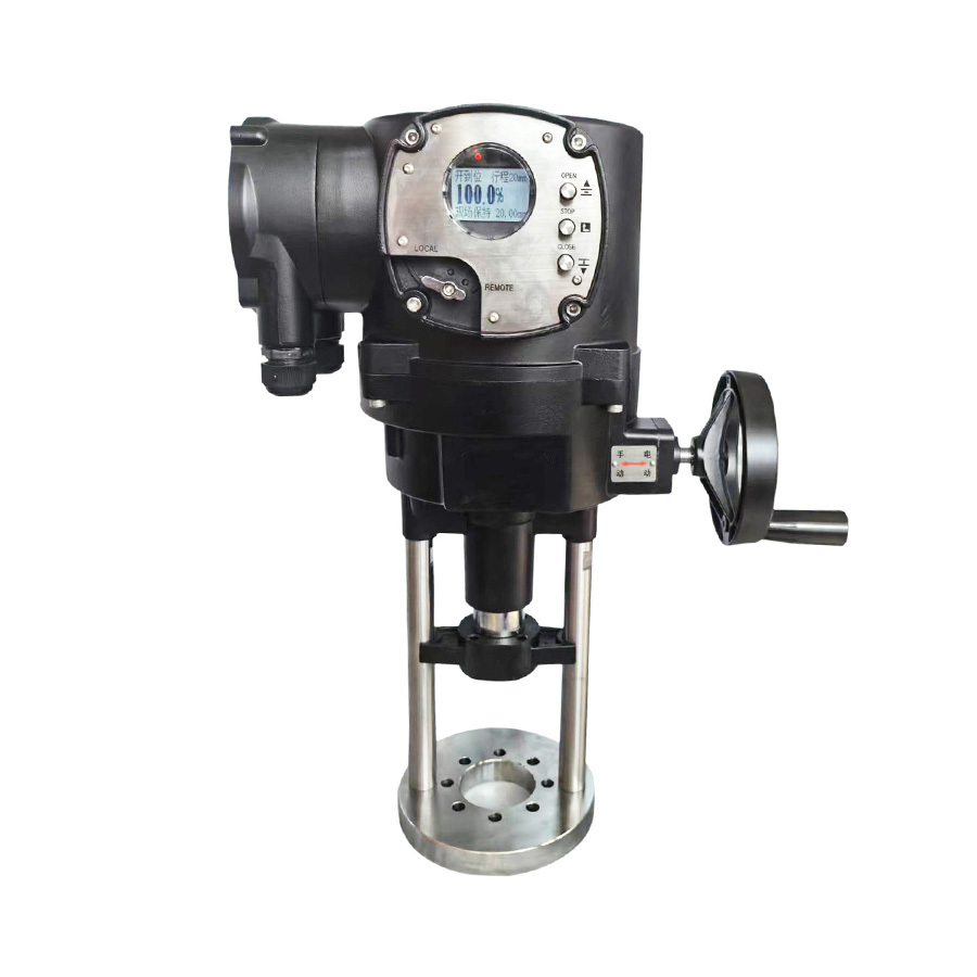
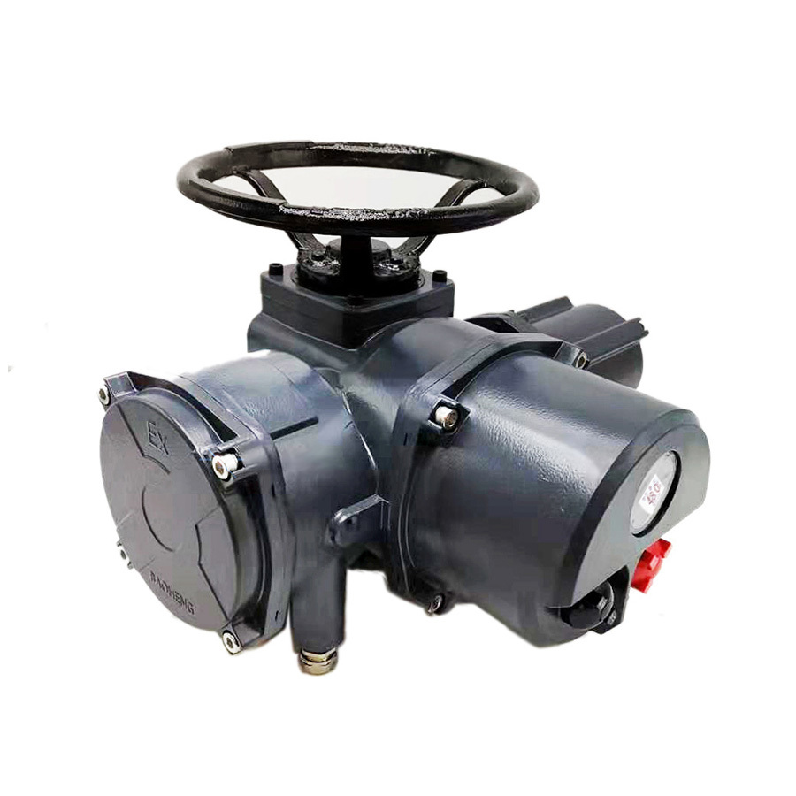
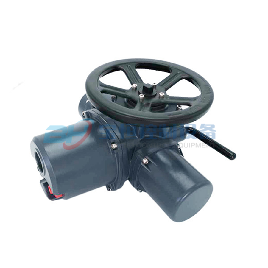
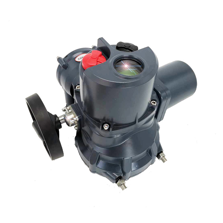
The mechanical transmission structure in the YMD series electric actuators adopts the mature technology of the MD series, and the electrical control box uses a fully digital design. Debugging and operation are controlled via an infrared remote control, and the main body is equipped with an operation knob to achieve non-intrusive settings and operations.
Keyword:
- Commodity name: YMD Series
Technical Features of YMD Series Products
The mechanical transmission structure in the YMD series electric actuators adopts the mature technology of the MD series, and the electrical control box uses a fully digital design. Debugging and operation are controlled via an infrared remote control, and the main body is equipped with an operation knob for non-intrusive settings and operations. The digital display can show the opening value, operating status, and various fault statuses of the actuator, facilitating user operation and maintenance.
Technical Advantages of YMD Series:
Fully digital design of the controller
Non-intrusive fully intelligent settings
Simple and convenient function settings
Application of encoder technology
Equipped with an operation knob
One-key function settings
Compact size and lightweight of the actuator
On-site human-machine dialogue window
Multiple installation methods available
Various input modes available
Basic Technical Index of YMD Series Products
(1) Input control signal: A) Analog signal 4-20mA, B) Passive contact control (optical isolation)
(2) Input channel resistance: 250 ohms
(3) Feedback signal: A) 4-20mA; B) Passive contact signal for fully open and fully closed positions
(4) Sensitivity: 0.75%~3%
(5) Damping characteristics: 0 oscillations
(6) Basic error: 1%~2.5%
(7) Protection level of the shell: IP65, IP67
(8) Motor insulation grade: B(F) grade
(9) Power supply voltage: AC 220V±10%~15%; AC 380V±10%
(10) Working system: 100% with more than 1200 starts per hour
(11) Operating environmental temperature: -20~+70℃
(12) Operating environmental humidity: ≤95% without condensation
(13) Insulation resistance: Between input terminals and the chassis ≥20MΩ
Between power terminals and the chassis ≥50MΩ
Between input terminals and power terminals ≥50MΩ
(14) Insulation strength: Between input terminals and shell 500V
Between input terminals and power terminals 500V
Between power terminals and shell 220V power supply 1500V
380V power supply 2000V
(15) Drift: Drift within 1.0% of rated stroke over 48 hours
The above indicators comply with the data specifications in JB/T8219-1999 "Electric Actuators for Industrial Process Measurement and Control"
Model of YMD Series Products
Specification Model Table of YMD Series Angle Stroke
| Operating Torque Nm |
Actuator Model Three-phase 380V |
Action Time S/90° |
Power KW |
Rated Current A |
Starting Current A |
Net Weight Kg |
| 150 |
YMD-15/F |
30/60 |
0.03 |
0.30 |
0.50 |
30 |
| 250 |
YMD-25/F |
30/60 |
0.03 |
0.30 |
0.50 |
30 |
| 600 |
YMD-60/F |
30/60 |
0.06 |
0.30 |
0.80 |
45 |
| 1000 |
YMA+RS100/F |
30/35/45/50 |
0.12 |
0.80 |
1.60 |
70 |
| 1600 |
YMA+RS160/F |
40/60 |
0.12 |
0.80 |
1.60 |
97 |
| 2500 |
YMA+RS250/F YMB+RS250/F |
65/100 20/30/40/60 |
0.20 0.37 |
0.90 1.10 |
2.20 4.50 |
121 125 |
| 4000 |
YMB+RS400/F |
30/40/50/70 |
0.50 |
1.50 |
4.50 |
165 |
| 6000 |
YMB+RS600/F |
40/55/76/104 |
1.00 |
2.70 |
14.0 |
190 |
| 8000 |
YMB+RS800/F |
78/104/129 |
0.80 |
2.50 |
13.0 |
220 |
| 10000 |
YMB+RS1000/F |
57/78/104/129 |
1.00 |
2.70 |
14.0 |
230 |
| 16000 |
YMB+RS1600/F |
73/91/125/165 |
1.50 |
3.40 |
20.0 |
250 |
| 25000 |
YMB+RS2500/F |
121/165/228/286 |
2.20 |
4.40 |
27.0 |
340 |
| 35000 |
YMB+RS3500/F |
150/208/286/390 |
3.00 |
7.20 |
37.0 |
470 |
| 50000 |
YMB+RS5000/F |
208/286/390 |
4.50 |
9.10 |
52.0 |
495 |
| Operating Torque Nm |
Actuator Model Single-phase 220V |
Action Time S/90° |
Power KW |
Rated Current A |
Starting Current A |
Net Weight Kg |
| 100 |
YMD-10/K |
25 |
0.03 |
0.60 |
0.90 |
15 |
| 250 |
YMD-25/K |
30/60 |
0.03 |
0.60 |
0.90 |
30 |
| 600 |
YMD-60/K |
30/60 |
0.06 |
1.20 |
1.70 |
45 |
| 1000 |
YMA+RS100/K |
35/45/50 |
0.15 |
2.00 |
3.00 |
70 |
| 1600 |
YMA+RS160/K |
40/60 |
0.15 |
2.00 |
3.00 |
97 |
| 2500 |
YMA+RS250/K YMB+RS250/K |
65/100 30/40/60 |
0.20 0.20 |
2.50 2.50 |
3.50 3.50 |
121 125 |
| 4000 |
YMB+RS400/K |
40/55/75 |
0.30 |
2.90 |
4.50 |
165 |
| 6000 |
YMB+RS600/K |
76/104/172 |
0.30 |
2.90 |
4.50 |
190 |
| 10000 |
YMB+RS1000/K |
104/129/194 |
0.40 |
3.50 |
14.0 |
230 |
| 16000 |
YMB+RS1600/K |
171/235 |
0.40 |
3.50 |
14.0 |
250 |
Note: When ordering, please indicate the angle stroke electric actuator as follows.
| Power head model |
Reducer code |
Output torque |
Power supply |
Stroke time |
Installation method |
Control method |
| YMB |
+RS |
160 |
/K |
30 |
H |
● |
| YMA - small torque YMB - large torque |
RS-angle stroke Z-straight stroke |
1600Nm |
K single-phase power supply F three-phase power supply |
30 seconds |
H is base type Z is direct connection type |
· Analog quantity adjustment type Y switch quantity adjustment type L switch two-position type |
YMD series straight stroke specification model table
Three-phase power supply 380V, 50Hz
| Operating thrust KN |
Model Three-phase 380V |
Action stroke mm |
Action speed mm/S |
Valve rod bolt F |
Flange connection D1 |
Flange inner diameter D2 |
Connection screw hole D3 |
Size A/B |
Power KW |
Current rated/start A |
Net Weight Kg |
| 6.4 |
YMA+Z64/F |
10-Z40 |
1.2/1.8 |
M8×1.25 M12×1.25 |
Φ80 Φ105 |
Φ60 Φ80 |
2-Φ10 4-Φ12 |
480/407 550/460 |
0.03 |
0.3/0.5 |
39 |
| 10 |
YMA+Z100/F |
25-60 |
1.2/1.8 |
M12×1.25 M16×1.5 |
Φ105 Φ118 |
Φ80 Φ95 |
4-Φ12 4-Φ12 |
550/460 591/460 |
0.12 |
0.8/1.6 |
41 |
| 16 |
YMB+Z160/F |
40-100 |
1.5/2.3 |
M16×1.5 M20×1.5 |
Φ118 Φ135 |
Φ95 Φ100 |
4-Φ12 6-Φ18 |
591/460 591/460 |
0.20 |
0.9/2.2 |
68 |
| 25 |
YMB+Z250/F |
40-100 |
1.4/2.7 |
M20×1.5 M27×2 |
Φ135 |
Φ100 |
6-Φ18 |
591/460 591/460 |
0.37 |
1.1/4.5 |
75 |
| 40 |
YMB+Z400/F |
Note: Non-national standard products must negotiate connection dimensions with the valve manufacturer. |
|||||||||
| 60 |
YMB+Z600/F |
||||||||||
| 100 |
YMB+Z1000/F |
||||||||||
| 150 |
YMB+Z1500/F |
||||||||||
Single-phase power supply 220V, 50Hz
| Operating thrust KN |
Model Single-phase 220V |
Action stroke mm |
Action speed mm/S |
Valve rod bolt F |
Flange connection D1 |
Flange inner diameter D2 |
Connection screw hole D3 |
Size A/B |
Power KW |
Current rated/start A |
Net Weight Kg |
| 6.4 |
YMA+Z64/K |
10-40 |
1.2/1.8 |
M8×1.25 M12×1.25 |
Φ80 Φ105 |
Φ60 Φ80 |
2-Φ10 4-Φ12 |
480/407 550/460 |
0.03 |
0.6/0.9 |
39 |
| 10 |
YMA+Z100/K |
25-60 |
1.2/1.8 |
M12×1.25 M16×1.5 |
Φ105 Φ118 |
Φ80 Φ95 |
4-Φ12 4-Φ12 |
550/460 591/460 |
0.15 |
2.0/3.0 |
41 |
| 16 |
YMB+Z160/K |
40-100 |
1.5/2.3 |
M16×1.5 M20×1.5 |
Φ118 Φ135 |
Φ95 Φ100 |
4-Φ12 6-Φ18 |
591/460 591/460 |
0.20 |
2.5/3.5 |
68 |
| 25 |
YMB+Z250/K |
40-100 |
1.4/2.7 |
M20×1.5 M27×2 |
Φ135 |
Φ100 |
6-Φ18 |
591/460 591/460 |
0.40 |
3.5/14 |
75 |
Note: When ordering, please indicate the following method for linear stroke electric actuators
| Power head model |
Reducer code |
Output thrust | Power supply |
Output speed | Action stroke |
Control method |
| YMB |
+Z |
6.4 | K |
1.2 | 25 |
● |
| YMA - small torque YMB - large torque |
RS-angle stroke Z-straight stroke |
6.4KN |
K single-phase power supply F three-phase power supply |
1.2 millimeters per second |
25mm |
· Analog adjustment type Y switch quantity adjustment type L switch two-position type |
Example: YMA+Z64/K1225· indicates that the output thrust of the linear stroke electric actuator is 6400 Newtons, single-phase power supply, speed is 1.2mm/s, stroke is 25 millimeters, and the control method is analog adjustment type.
Message


