


MD Series
The MD series electric actuators are designed with an internationally popular modular structure. The products and parts are meticulously considered in terms of generalization, standardization, and serialization, significantly reducing the variety and quantity of spare parts needed by users during use and maintenance, thereby lowering maintenance and operating costs.
- Commodity name: MD Series
Technical Features of MD Series Products
The MD series electric actuators adopt an internationally popular modular structure in design, with detailed consideration for the generalization, standardization, and serialization of products and parts, greatly reducing the variety and quantity of spare parts needed by users during use and maintenance, thus lowering maintenance and operating costs.
The motors use high torque, low inertia single-phase or three-phase special motors, all equipped with overheating protection relays, and the motor rotor output end is directly connected to the shaft gear, resulting in a short response time.
The mechanical reducer uses a planetary gear reduction combined with a worm gear drive structure, which not only has high mechanical efficiency but also possesses mechanical self-locking characteristics, ensuring high reliability. It also uses long-lasting lithium-based grease, ensuring that the actuator does not require replacement or maintenance during a major overhaul period and can be installed and used at any angle.
The MD series electric actuators use advanced integrated circuit devices in their electrical components, with the power drive part being a solid-state relay without mechanical contacts, offering a long service life and requiring no daily maintenance, capable of operating up to 1200 times per hour, making it particularly suitable for applications in environments with high automation rates and frequent operations.
Basic Features of MD Series:Equipped with adjustment functions, simple and reliable
1. Motor Overheating Protection
2. Signal Loss Protection
3. Over Torque Protection
4. Mechanical Limit Protection
5. Electrical Limit Protection
6. Phase Loss and Phase Error Protection
7. Shell Protection IP65
8. On-site Handwheel Operation
9. Standard Current Signal Control
10. Passive Contact Control
11. Portable Limit Adjustment
12. Electronic Integrated Structure
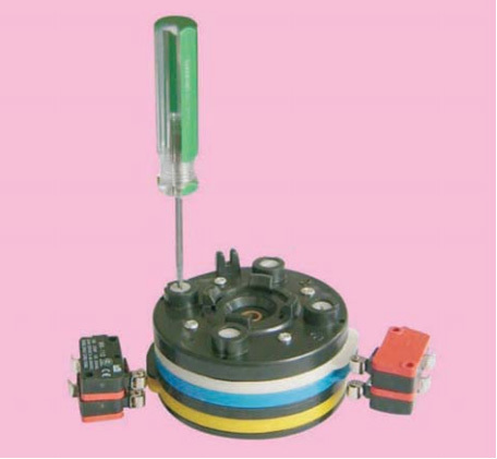
Simple and portable limit adjustment
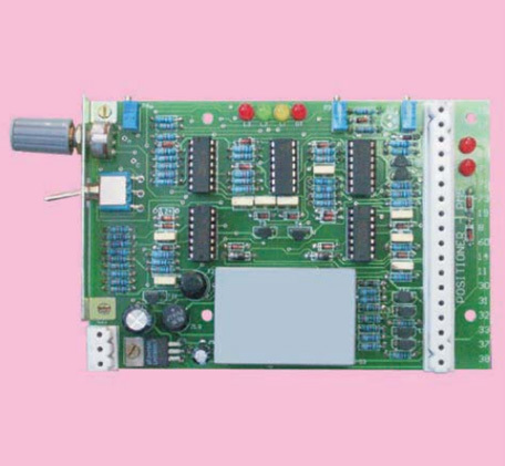
Compact single-board amplifier
Classification of MD Series Products
(1) Angle Stroke Electric Actuator: Output Torque 100Nm--50000Nm
(2) Linear Stroke Electric Actuator: Output Thrust 6.4KN--150KN
(3) Multi-turn Electric Actuator: Output Torque 40Nm--4000Nm
Basic Technical Index of MD Series Products
(1) Input Control Signal: A) Analog Signal 4-20mA, B) Passive Contact Control
(2) Input Channel Resistance: 250 Ohms
(3) Feedback Signal: A) 4-20mA; B) Passive contact signal for fully open and fully closed positions
(4) Sensitivity: 1%~3%
(5) Damping Characteristics: 0 Oscillations
(6) Basic Error: 1%~2.5%
(7) Shell Protection Level: IP65
(8) Motor Insulation Class: B(F) Class
(9) Power Supply Voltage: AC 220V±10%~15%; AC 380V±10%
(10) Working System: 100% with more than 1200 starts per hour
(11) Operating Environment Temperature: -20~+70℃
(12) Operating Environment Humidity: ≤95% No Condensation
(13) Insulation Resistance: Input Terminal to Chassis ≥20MΩ
Power Supply Terminal to Chassis ≥50MΩ
Input Terminal to Power Supply Terminal ≥50MΩ
(14) Insulation Strength: Input Terminal to Shell 500V
Input Terminal to Power Supply Terminal 500V
Power Supply Terminal to Shell 220V Power Supply 1500V
380V Power Supply 2000V
(15) Drift: Drift within 1.0% of rated stroke over 48 hours
The above indicators comply with the data specifications in JB/T8219-1999 "Electric Actuators for Industrial Process Measurement and Control"
Model of MD Series Products
Model of MD Series Angle Stroke Products
Angle stroke electric actuators are divided into direct connection and base-mounted (with output arm) types based on installation methods. The direct connection type is suitable for direct connection with valves, featuring a compact structure (please consider the temperature of the medium on-site and the feasibility of maintenance). The base-mounted type is characterized by easy installation and maintenance (generally requires the use of our factory's GZ type spherical hinge for installation; if users need spherical hinges, please specify separately in the order contract).
The following are the specifications and installation dimensions of angle stroke electric actuators.
MD Series Angle Stroke Electric Actuator Model Table
| Operating Torque Nm |
Actuator Model Three-phase 380V |
Action Time S/90° |
Power KW |
Rated Current A |
Starting Current A |
Net Weight Kg |
| 100 |
MD-10/F |
25 |
0.03 |
0.30 |
0.50 |
15 |
| 250 |
MD-25/F |
30/60 |
0.03 |
0.30 |
0.50 |
30 |
| 600 |
MD-60/F |
30/60 |
0.06 |
0.30 |
0.80 |
45 |
| 1000 |
MA+RS100/F |
30/35/40/50 |
0.12 |
0.80 |
1.60 |
70 |
| 1600 |
MA+RS160/F |
40/60 |
0.12 |
0.80 |
1.60 |
97 |
| 2500 |
MA+RS250/F MB+RS250/F |
65/100 20/30/40/60 |
0.20 0.37 |
0.90 1.10 |
2.20 4.50 |
121 125 |
| 4000 |
MB+RS400/F |
30/40/50/70 |
0.50 |
1.50 |
4.50 |
165 |
| 6000 |
MB+RS600/F |
40/55/76/104 |
1.00 |
2.70 |
14.0 |
190 |
| 8000 |
MB+RS800/F |
78/104/129 |
0.80 |
2.50 |
13.0 |
220 |
| 10000 |
MB+RS1000/F |
57/78/104/129 |
1.00 |
2.70 |
14.0 |
230 |
| 16000 |
MB+RS1600/F |
73/91/125/165 |
1.50 |
3.40 |
20.0 |
250 |
| 25000 |
MB+RS2500/F |
121/165/228/286 |
2.20 |
4.40 |
27.0 |
340 |
| 35000 |
MB+RS3500/F |
150/208/286/390 |
3.00 |
7.20 |
37.0 |
470 |
| 50000 |
MB+RS5000/F |
208/286/390 |
4.50 |
9.10 |
52.0 |
495 |
The weights indicated in the table above are for base-mounted products, while the direct-coupled weights are in the connection size table.
Note: When ordering, please indicate the angle stroke electric actuator using the following method.
| Power head base model |
Reducer code |
Output torque |
Power supply |
Stroke time |
Installation method |
Control method |
| MB |
+RS |
160 |
/K |
30 seconds |
H |
T |
| MA - small torque MB - large torque |
RS - angle stroke Z - direct stroke |
1600Nm |
K single-phase power supply F three-phase power supply |
|
H for base-mounted Z for direct-coupled |
T for integrated type Y for remote control type |
Example: MB+RS160/K30HT indicates an angle stroke actuator with an output torque of 1600Nm, single-phase power supply, 90° stroke time of 30 seconds, base-mounted installation method, and integrated control method.
MB+RS400/F70ZY indicates an angle stroke actuator with an output torque of 4000Nm, three-phase power supply, 90° stroke time of 70 seconds, direct-coupled installation method, and remote control type.
MD Series Angle Stroke Electric Actuator Model Table
| Operating Torque Nm |
Actuator Model Single-phase 220V |
Action Time S/90° |
Power KW |
Rated Current A |
Starting Current A |
Net Weight Kg |
| 100 |
MD-10/K |
25 |
0.03 |
0.60 |
0.90 |
15 |
| 250 |
MD-25/K |
30/60 |
0.03 |
0.60 |
0.90 |
30 |
| 600 |
MD-60/K |
30/60 |
0.06 |
1.20 |
1.70 |
45 |
| 1000 |
MA+RS100/K |
35/45/50 |
0.15 |
2.00 |
3.00 |
70 |
| 1600 |
MA+RS160/K |
40/60 |
0.15 |
2.00 |
3.00 |
97 |
| 2500 |
MA+RS250/K MB+RS250/K |
65/100 30/40/60 |
0.20 0.20 |
2.50 2.50 |
3.50 3.50 |
121 125 |
| 4000 |
MB+RS400/K |
40/55/75 |
0.30 |
2.90 |
4.50 |
165 |
| 6000 |
MB+RS600/K |
76/104/172 |
0.30 |
2.90 |
4.50 |
190 |
| 10000 |
MB+RS1000/K |
104/129/194 |
0.40 |
3.50 |
14.0 |
230 |
| 16000 |
MB+RS1600/K |
171/235 |
0.40 |
3.50 |
14.0 |
250 |
MD series direct stroke models and installation dimensions
The direct stroke electric actuator is mainly used with various linear operating valves such as: regulating valves, sleeve valves, etc. Installation and debugging are simple, and performance is reliable.
Three-phase power supply 380V, 50Hz
| Operating thrust KN |
Model Three-phase 380V |
Action stroke mm |
Action speed mm/s |
Rod bolt F |
Flange connection D1 |
Flange inner diameter D2 |
Connection screw hole D3 |
Overall dimensions A/B |
Power KW |
Current rated/start A |
Net Weight Kg |
| 6.4 |
MA+Z64/F |
10-40 |
1.2/1.8 |
M8 ×1.25 M12 ×1.25 |
Φ80 Φ105 |
Φ60 Φ80 |
2-Φ10 4-Φ12 |
480/407 550/460 |
0.03 |
0.3/0.5 |
39 |
| 10 |
MA+Z100/F |
25-60 |
1.2/1.8 |
M12 ×1.25 M16 ×1.5 |
Φ105 Φ118 |
Φ80 Φ95 |
4-Φ12 4-Φ12 |
550/460 591/460 |
0.12 |
0.8/1.6 |
41 |
| 16 |
MB+Z160/F |
40-100 |
1.5/2.3 |
M16 ×1.5 M20 ×1.5 |
Φ118 Φ135 |
Φ95 Φ100 |
4-Φ12 6-Φ18 |
591/460 591/460 |
0.20 |
0.9/2.2 |
68 |
| 25 |
MB+Z250/F |
40-100 |
1.4/2.7 |
M20 ×1.5 M27 ×2 |
Φ135 |
Φ100 |
6-Φ18 |
591/460 591/460 |
0.37 |
1.1/4.5 |
75 |
| 40 |
MB+Z400/F |
Note: Non-national standard products must negotiate connection dimensions with the valve manufacturer. |
|||||||||
| 60 |
MB+Z600/F |
||||||||||
| 100 |
MB+Z1000/F |
||||||||||
| 150 |
MB+Z1500/F |
||||||||||
Single-phase power supply 220V, 50Hz
| Operating thrust KN |
Model Single-phase 220V |
Action stroke mm |
Action speed mm/s |
Rod bolt F |
Flange connection D1 |
Flange inner diameter D2 |
Connection screw hole D3 |
Overall dimensions A/B |
Power KW |
Current rated/start A |
Net Weight Kg |
| 6.4 |
MA+Z64/K |
10-40 |
1.2/1.8 |
M8 ×1.25 M12 ×1.25 |
Φ80 Φ105 |
Φ60 Φ80 |
2-Φ10 4-Φ12 |
480/407 550/460 |
0.03 |
0.6/0.9 |
39 |
| 10 |
MA+Z100/K |
25-60 |
1.2/1.8 |
M12 ×1.25 M16 ×1.5 |
Φ105 Φ118 |
Φ80 Φ95 |
4-Φ12 4-Φ12 |
550/460 591/460 |
0.15 |
2.0/3.0 |
41 |
| 16 |
MB+Z160/K |
40-100 |
1.5/2.3 |
M16 ×1.5 M20 ×1.5 |
Φ118 Φ135 |
Φ95 Φ100 |
4-Φ12 6-Φ18 |
591/460 591/460 |
0.20 |
2.5/3.5 |
68 |
| 25 |
MB+Z250/K |
40-100 |
1.4/2.7 |
M20 ×1.5 M27 ×1.5 |
Φ135 |
Φ100 |
6-Φ18 |
591/460 591/460 |
0.40 |
3.5/14 |
75 |
Message


Contact Us
Service Hotline:
+86-22-23785511 23785522 23785533
E-mail:baoheng@263.net
Address: No.2, Haitai Development Road 1, Huayuan Industrial Zone, Tianjin (Huanwai)