MN Series
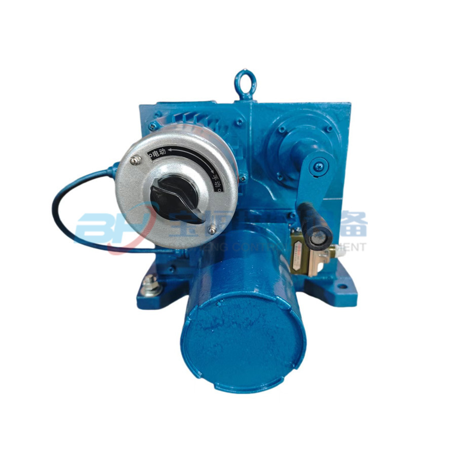
The MN series electric actuators are a new generation of electric actuators independently developed by our company based on mature existing products, combined with domestic and international experience and technology. This product has advantages such as good anti-interference technology, convenient debugging operations, and an intuitive human-machine dialogue interface. It is suitable for automated control of gate valves, ball valves, shut-off valves, throttle valves, diaphragm valves, etc., and can achieve both on-site and remote operation of controlled valves. This product can be widely used in industrial fields such as electric power, building materials, metallurgy, petroleum, chemical industry, municipal, and new energy.
- Commodity name: MN Series
1. Product Introduction
The MN series electric actuators are a new generation of electric actuators independently developed by our company based on existing mature products, combining domestic and international experience and technology. This product features excellent anti-interference technology, convenient debugging operations, and an intuitive human-machine dialogue interface. It is suitable for the automation control of gate valves, ball valves, globe valves, throttle valves, diaphragm valves, etc., and can achieve both on-site and remote operation of controlled valves. This product can be widely used in industrial fields such as electric power, building materials, metallurgy, petroleum, chemical industry, municipal, and new energy.
The performance and technical specifications of the MN series electric actuators comply with JB/T8219-2016 "Electric Actuators for Industrial Process Measurement and Control Systems" and JB/T8528-1997 "Technical Conditions for General Type Electric Devices for Valves". The performance of the explosion-proof type complies with GB3836.1-2000 "Electrical Equipment for Explosive Gas Atmospheres - Part 1: General Requirements", GB3836.2-2000 "Electrical Equipment for Explosive Gas Atmospheres - Part 2: Flameproof Type 'd'", JB/T8529-1997 "Technical Conditions for Flameproof Electric Devices", GB12476.1-2013 "Electrical Equipment for Flammable Dust Atmospheres - Part 1: General Requirements" and GB12476.5-2013 "Electrical Equipment for Flammable Dust Atmospheres - Part 5: Protection by Enclosure 'tD'".
2. Product Features
1. Shell Protection
The actuator shell is made of high-pressure cast aluminum alloy, with an epoxy powder coating on the surface, providing strong UV resistance, corrosion resistance, and high fullness, which significantly improves the service life and self-cleaning properties of the coating, making it suitable for various harsh production environments. The shell protection level reaches IP67 or higher. In explosion-proof locations, it meets the requirements of Exd II BT4 standards.
2. Power Transmission
The main transmission of the actuator consists of worm gears made of high-strength alloy materials, and precise processing minimizes transmission resistance. Coupled with lubricating oil suitable for different environmental temperatures, it provides comprehensive lubrication, making it more adaptable to various working conditions and maximizing service life.
3. Motor Monitoring and Protection
The motor uses a low-inertia, high-torque servo motor, allowing it to quickly reach peak torque after starting.
Overheat Protection: The motor is equipped with a precise temperature sensor. When the temperature exceeds the rated value, the motor operation is prohibited, and an overheat alarm message is displayed to prevent damage caused by motor overheating.
Instant Reversal Protection: Using instant reversal delay control technology, when a reverse operation signal is received during the actuator's operation, the control system will first stop the machine, then execute the reverse action after a delay, preventing damage to mechanical transmission components.
Electronic Braking: The adjustable electric actuator ensures that the valve stops at the set valve position through dead zone settings and electronic braking.
4. Output Interface
The actuator flange complies with ISO5210/5211 (GB12222/12223) standards, and also provides flanges that meet JB2920 standards, with special customization available according to customer requirements.
5. Human-Machine Interface LCD Display
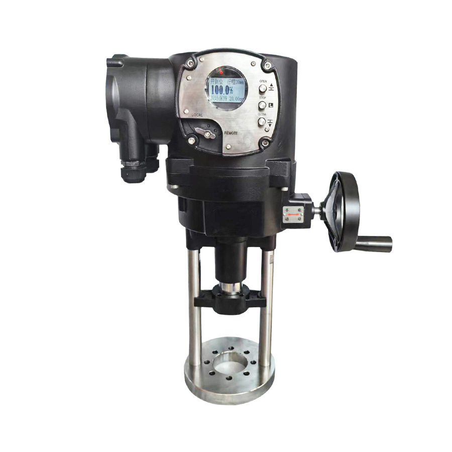
It uses a high-brightness, high-definition LCD screen and a simple and convenient operating panel, displaying torque, valve position, limit settings, and other working states and alarms in Chinese and numbers, facilitating on-site operation and parameter setting, clearly observable even at night.
6. Highly Integrated Control Circuit
The mature and reliable control circuit design scheme reduces the number of discrete components through large-scale integrated circuit technology, improving overall reliability; it employs an inertia-adaptive stepping control strategy to effectively solve the inertia problem of the motor, achieving accurate positioning and improving control precision.
The electrical control module, as a key part of the intelligent system, features remote control, emergency action, remote holding, remote opening, and remote closing functions, elevating the electric operation mode of the valve to a higher level.
· Provides on-site programmable monostable relay feedback
· Provides alarm monostable relay feedback
· Input and output signal channels are optically isolated (can withstand 2000V surge voltage)
Position feedback 4-20mA signal, load resistance: 50Ω to 750Ω, accuracy: adjustable from 0.5% to 3%.
7. Sealing Structure
The actuator adopts a double-seal design structure, with a circular structure on the combined surface and a long stop with a sealing ring combination, ensuring good sealing performance and ensuring that the actuator is completely waterproof, dustproof, and prevents the intrusion of various gases; the standard product protection level is IP67, and can reach up to IP68.
8. Intelligent Infrared Remote Control Function
The actuator uses advanced infrared remote control technology, allowing human-machine dialogue through a sealed dialogue window without opening the actuator box cover. The intelligent remote control includes functions such as remote switch control, remote automatic control, and on-site stop. The remote assistance operation function replaces the single manual operation system, making it more convenient, simple, safe, and effective.
9. Intelligent Self-Detection, Diagnosis, and Protection Function
It has an intelligent self-check error alarm function. When the electric actuator is powered on, it automatically checks the actuator's functional components to ensure there are no faults; during operation, it monitors the functional components in real-time, and if a fault occurs, the actuator immediately prohibits operation and simultaneously issues on-site and remote alarm signals, allowing users to quickly identify the cause of the fault and promptly eliminate it to restore operation.
Phase Sequence Automatic Recognition: Using optically isolated phase sequence automatic recognition circuit, users can connect the power line in any phase sequence, and the valve will always operate in the correct direction.
Phase Loss Protection: If any phase of the three-phase power supply is missing, the motor operation is prohibited, and a phase loss alarm message is displayed.
Prohibition Delay Protection Function: When control models are input simultaneously, the system prohibits operation and automatically delays the direction change.
ESD Protection: Provides flexible emergency protection functions, with emergency action control methods set through parameters, allowing for individual setting of action methods during emergency protection, such as fully open, fully closed, or holding position. (Intelligent type)
Control status protection: The mechanical lock on the electrical box cover can lock the remote, on-site, or stop status to prevent misoperation; to change parameter settings, a Password must be entered to access the settings interface.
Intelligent network security protection (optional): Supports dual redundant field bus communication.
9. On-site control
Using a magnetic rotary switch, the control status can be switched between on-site and remote while completely isolated from the electrical box, allowing for on-site valve control and parameter setting of electric devices (intelligent type).
10. Bus control function
The communication module adopts an independent structure stacked on the main board, meeting the needs of different communication media and different communication protocol systems. Currently supported communication protocols include Modbus RTU, PROFIBUS-DPV0/DPV1, HART, etc.
11. Precise valve position stroke measurement and protection
The actuator uses an absolute encoder to measure the valve position stroke, providing high angular resolution; the encoder is a magnetic-electric integrated type, and in the event of power loss, manual operation of the actuator does not risk losing the valve position. Advanced boundary anti-jitter technology is employed to ensure high-speed, stable, and reliable output data, effectively improving the stability and reliability of the system.
12. Manual/Electric operation
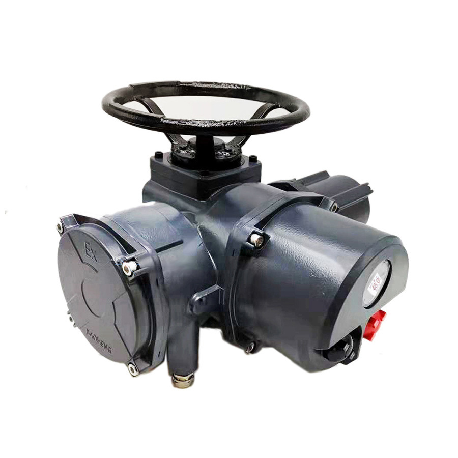
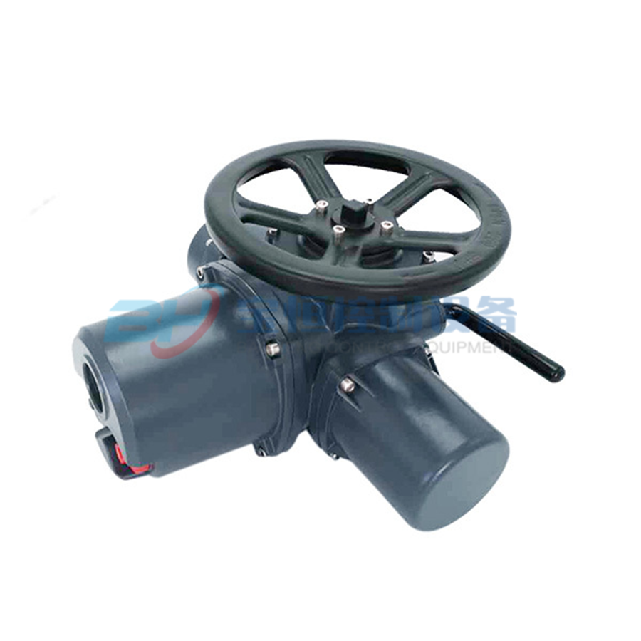
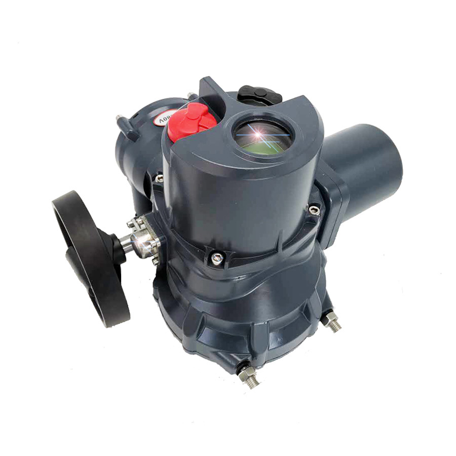
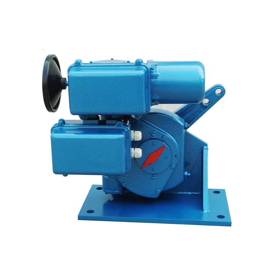
The MN series electric actuators are divided into top-mounted handwheels and side-mounted handwheels based on the installation position of the handwheel. Among them, the top-mounted handwheel is electric priority, while the side-mounted is manual priority. When manual operation is needed, simply switch the clutch handle. The operation of the top-mounted handwheel involves pushing the manual clutch handle towards the handwheel direction, where noticeable resistance indicates it can be manually operated; during electric operation, the clutch handle automatically resets. For the side-mounted handwheel, the locking pin must first be pulled out, and the manual shaft pushed inward; at this point, the locking pin locks the manual shaft, allowing for manual operation by turning the handwheel; after manual operation, release the handwheel and pull out the locking pin, allowing the manual shaft to automatically pop back to the electric state under the action of the compressed spring.
13. Torque measurement
The professionally designed torque measurement system can achieve overload protection for the actuator.
The mechanical torque measurement system achieves torque measurement by using the deformation of a force measuring spring. The position of the torque switch can be adjusted to achieve torque adjustment.
Electronic torque measurement: By detecting the real-time current, voltage, and magnetic flux of the motor, combined with a microcontroller for comprehensive calculation, the output torque is obtained, allowing for continuous measurement and real-time monitoring, which improves the reliability of the system. (Optional)
3. Classification of electric actuators
Classified by the motion mode of the driven device: MN multi-turn and MN+RS partial turn;
Classified by the operating environment of the actuator: outdoor type and explosion-proof type;
Classified by the control performance of the actuator: ordinary type, intelligent type;
Classified by the control method of the actuator: basic type, switch type, regulating type.
4. Model representation method
When ordering, please indicate the electric actuator using the following method.
Power head base type | Reducer code | Output torque | Power source | Stroke time | Connection method | Control method |
MN | +RS | 250 | /F | 30 | H | ZT |
MN-Multi-turn | RS-Angular stroke | 2500 Nm | K Single-phase power supply F Three-phase power supply | 30 seconds | H-Base type Z-Direct connection type | Basic type - no letter representation S-Overall switch type M-Overall regulating type IS-Intelligent switch type (non-intrusive) IM-Intelligent regulating type (non-intrusive) |
Example: MN-10/KIS indicates a multi-turn actuator with an output torque of 100Nm, single-phase power supply, intelligent switch type.
MN+RS250/F30HM indicates a partial turn actuator with an output torque of 2500Nm, three-phase power supply, 90° stroke time of 30 seconds, base type, overall regulating type.
5. Basic technical index of the product
● Input control signal: A) Analog signal 4~20mA; B) Passive contact control
● Input channel resistance: 250 ohms
● Feedback signal: A) 4~20mA; B) Passive contact signal for fully open and fully closed positions
● Sensitivity: 0.5%~3%
● Damping characteristics: 0 oscillations
● Basic error: 1%~1.5%
● Shell protection level: standard IP67 (special order IP68)
● Motor insulation grade: F grade
● Power supply voltage: AC220V ±10%~15%; AC380V ±10%; optional power supply: AC110~440V, 50, 60Hz (must be specified when ordering).
● Working system: switch type is 30%, within 15 minutes; regulating type is 50%, with startup times <600 times per hour; 100%, with startup times <1200 times per hour.
● Operating environment temperature: -20℃~+70℃
● Operating environment humidity: ≤95% without condensation.
● Insulation resistance: Between input terminals and the casing: ≥20MΩ; Between power terminals and the casing: ≥50MΩ; Between input terminals and power terminals: ≥50MΩ
● Insulation strength: Between input terminals and casing 500V; Between input terminals and power terminals 500V; Between power terminals and casing 220V power 1500V, 380V power 2000V
● Drift: Drift over 48 hours does not exceed 1.0% of the rated stroke
● Explosion-proof mark: Exd II BT4
Message


